Wang Laboratories Professional Computer (PC)
I picked up this really early IBM PC 'clone', which was originally released in April 1982, nearly a year before the famous Compaq Portable. However, unlike most other clones, it is only somewhat software compatible, and has completely incompatible hardware.
Unfortunately, I don't have the proprietary keyboard or monitor, which will make testing more difficult.
Work done:
- Inspection
- Create a keyboard interface
- Create a monitor adapter
Exterior inspection:
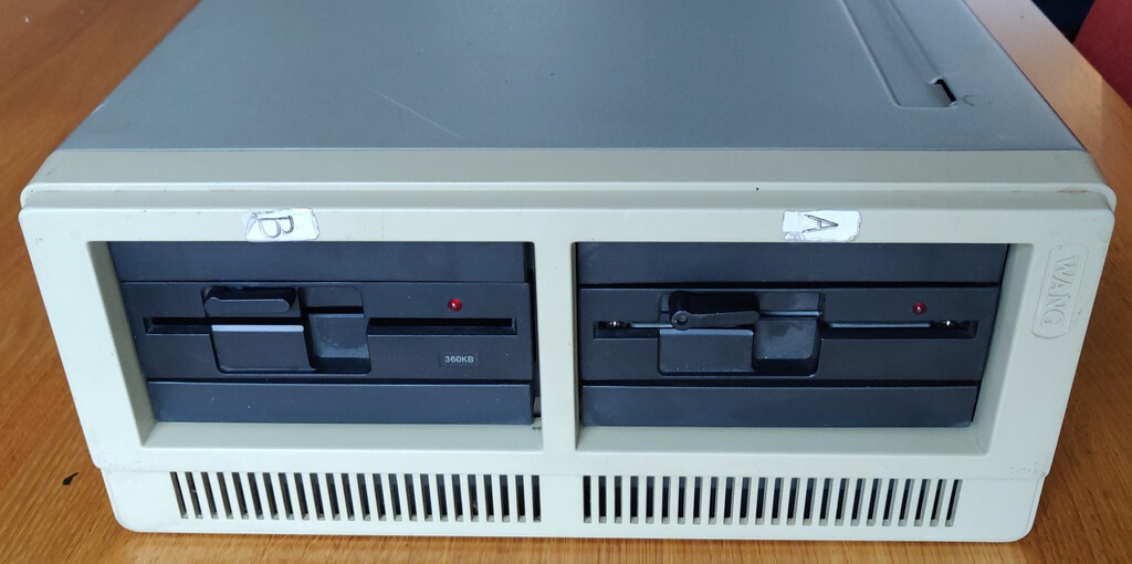
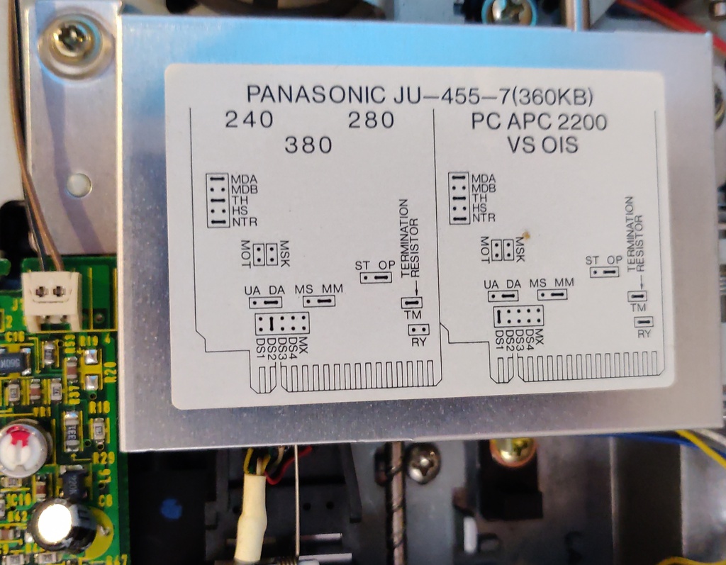
This computer is very bulky and heavy, even larger than an IBM 5150. At the front are two 360K floppy drives. The drives are not identical, so it's likely one was either a replacement or upgrade:
At the back are 5 expansion slots and the bottom cards are part of the main logic board:


Internal inspection:
The case is one large piece of steel, when the computer is placed on it's back it can be easily removed.
On the bottom this reveals the huge main logic board, which aside from the CPU and 256 KB of memory also contains the floppy controller, keyboard, serial and parallel connectors.

On the side is a card cage which contains all the expansion cards, these can be easily removed using the plastic latch.

On the top are the floppy drives.

Expansion cards
The expansion cards are equally large, measuring around the same as a sheet of A4 paper.
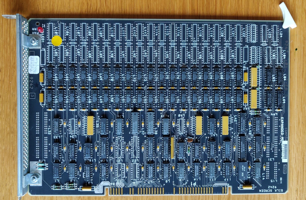
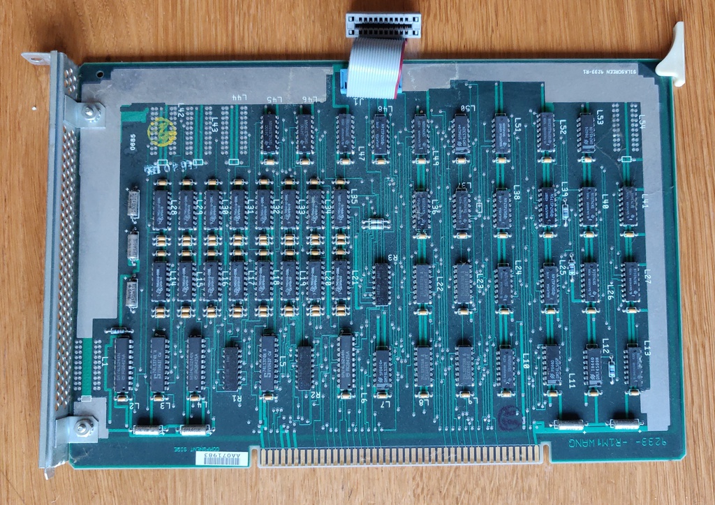
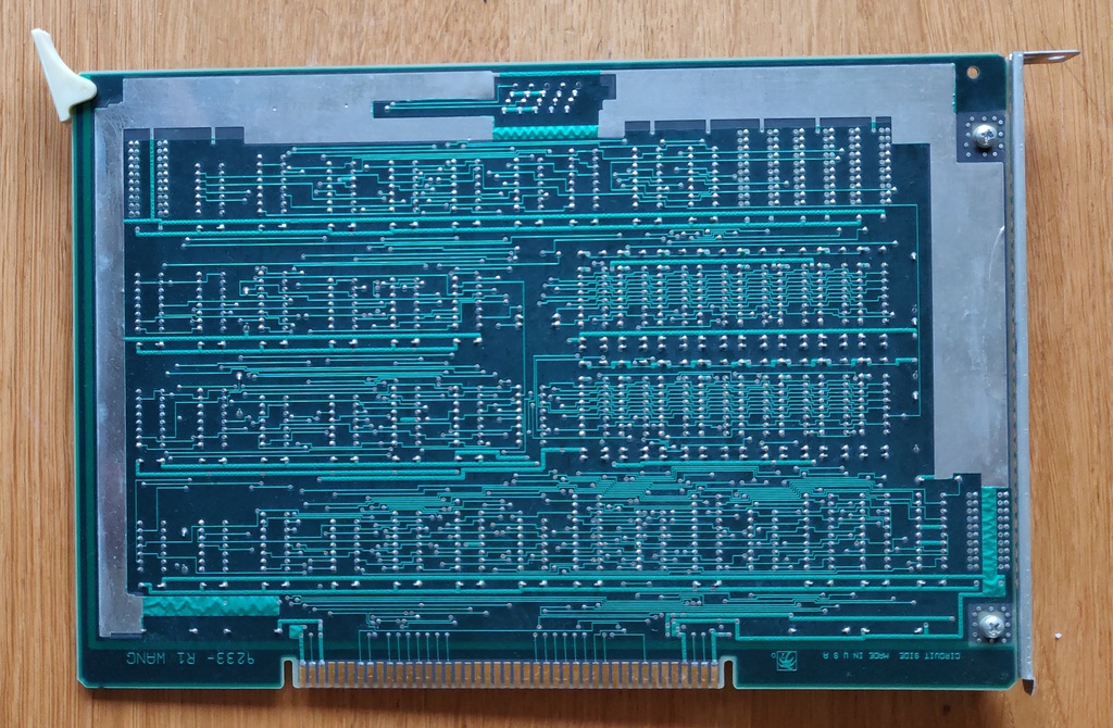
This is the first of two memory expansion cards, providing an additional 128K of RAM:
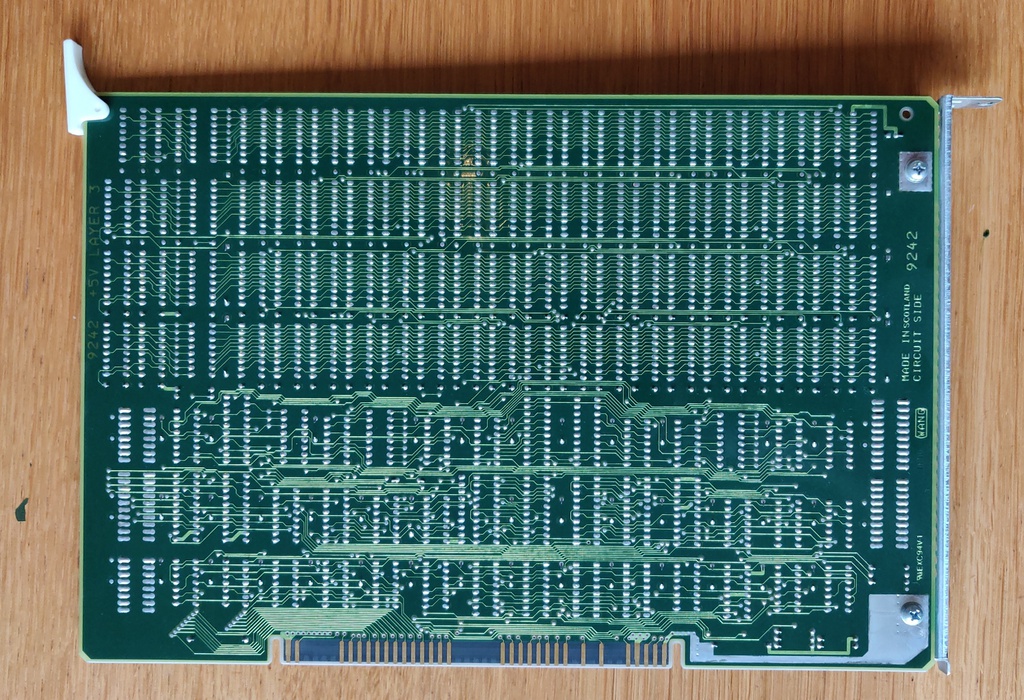
The second memory expansion card is unlabelled, but likely is 128K to bring the overall memory to the maximum of 640K:
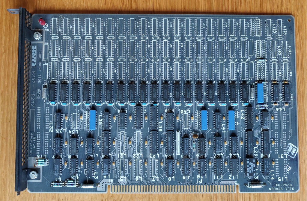
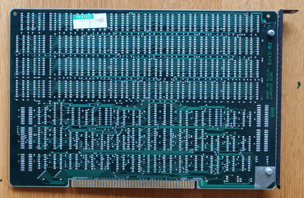
Next is a monochrome, text only video card, similar to (but certainly not compatible with) the IBM MDA card. Aside from video, there is also a connector to provide power to the monitor.
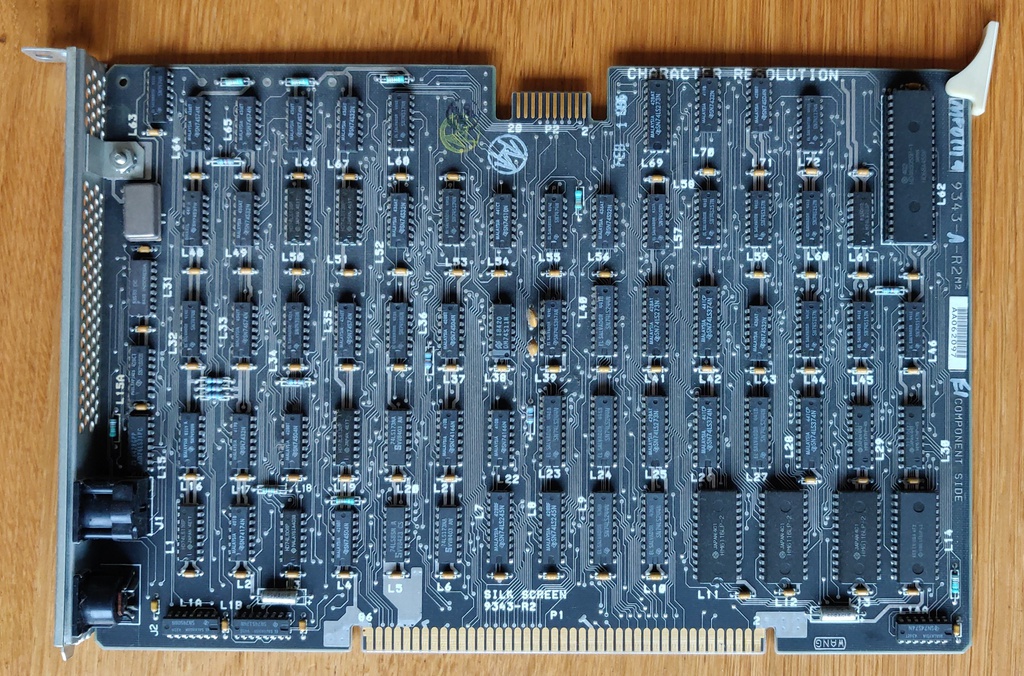
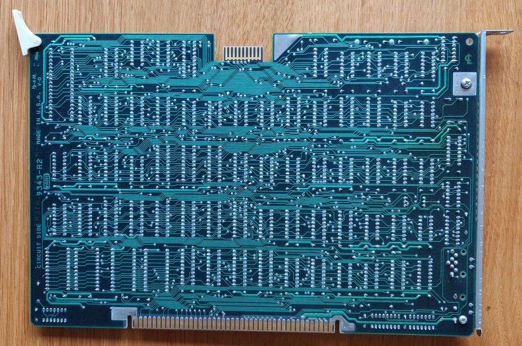
Lastly, a graphics expansion card, which connects directly to the graphics card using a ribbon cable to upgrade it with graphics capabilities:
Serial console
Without the proprietary keyboard or monitor, testing is more difficult. Luckily, the documentation states that when no video card is present, the serial port will be used for output instead. However, this will only show the POST information, since MS-DOS doesn't support serial console directly.
Keyboard adapter
I decided to tackle the keyboard issue first. After studying the Technical Reference Manual, I found that Wang chose a somewhat strange, but easy to implement keyboard protocol. Basically it's a bidirectional 5v RS-232 connection at 65200 baud, where the computer sends instructions to control the LEDs, speaker and general behaviour of the keyboard and the keyboard sends scan codes.
I built a functioning prototype of PS/2 to Wang keyboard adapter:
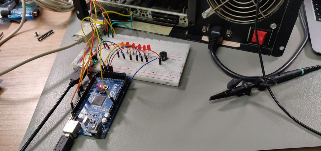
And published by code on GitHub. In the future, I'm planning to make a proper PCB with a ATmega328 to perform this task.
Monitor adapter
The Wang PC is equipped with a proprietary graphics adapter, which run at a 800x300 resolution and isn't compatible with regular MDA or similar graphics. But since it does use the same 5v TTL signal levels as I was able to adapter a RGB2HDMI adapter to work with it.
Once the settings have been fully fine-tuned, I will open a pull request to add the Wang to the official list of supported computers.
First boot
Now that I had graphics, it was time to boot the computer for the first time. In the meantime I had purchased some manuals with original Wang floppies.
Unfortunately, this was met with immediate disappointment:
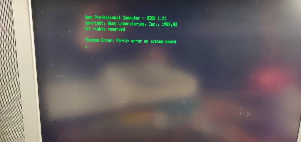
Luckily, one of the floppies I received with the manuals was a diagnostics floppy, so I gave it a try straight away:
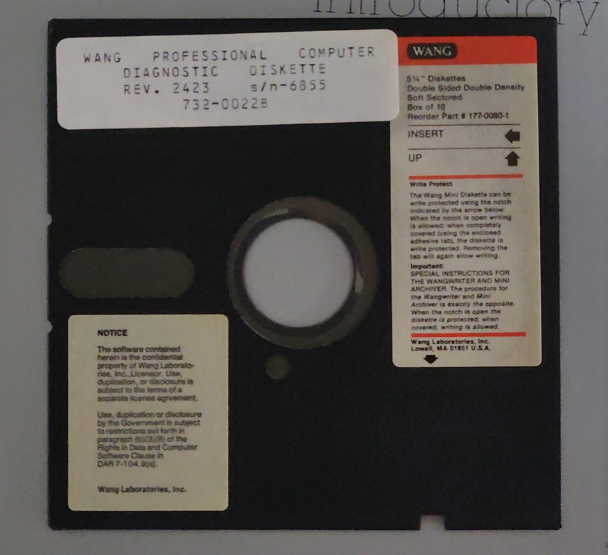
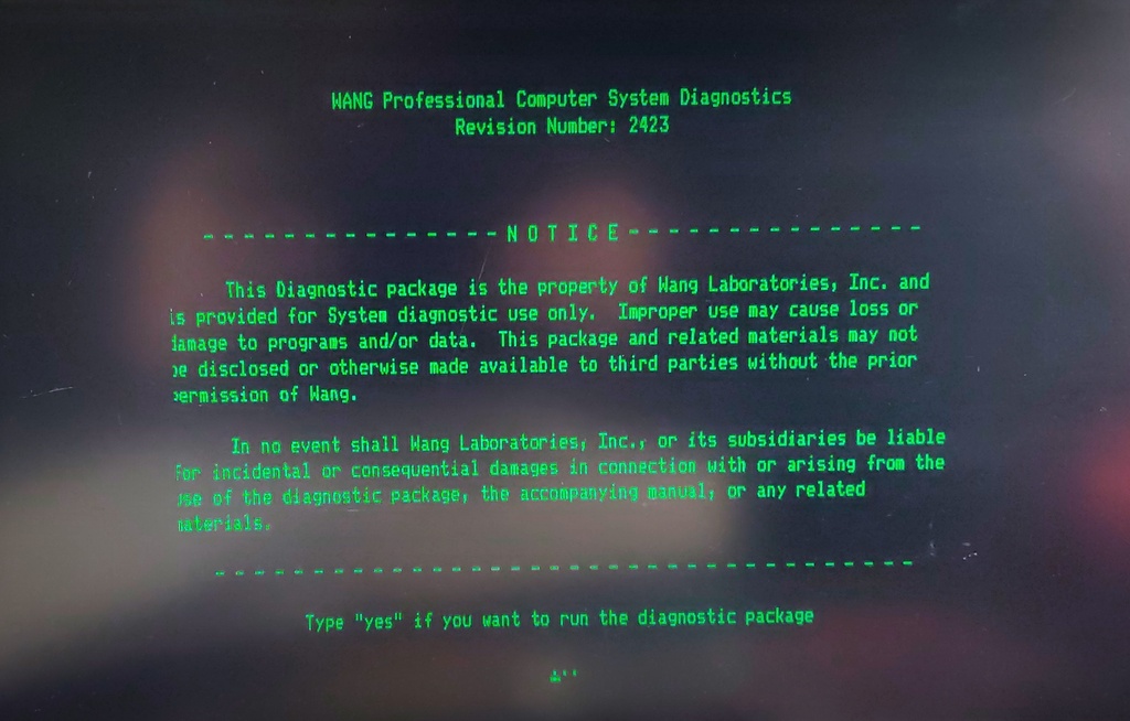
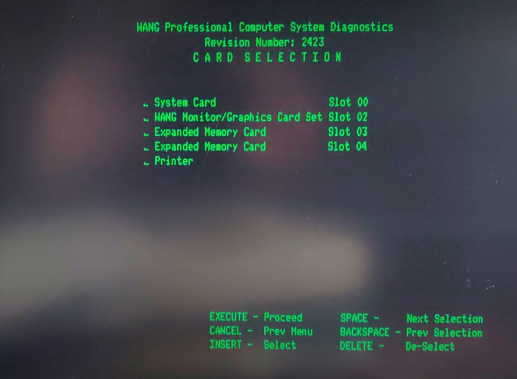
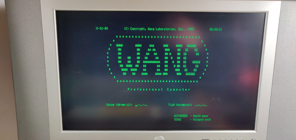
The diagnostics found that the only issue was with the 128K memory expansion card. Once I removed it, I was able to boot normally:
Faulty memory expansion board
The memory expansion board is proving exceptionally difficult to troubleshoot, especially since no schematics for it a published.
From the Technical Reference Manual, it appears that the card itself performs parity checks on the data and raises an NMI (non-maskable interrupt) when an error is detected. It also lights up an LED on the expansion board.
I made several attempts to check the memory chips with my logic analyser, but didn't manage to get much information since it's difficult to accurate clock the raster addressing and in timing mode the analyser doesn't have sufficient memory to catch enough usable data. However, I was able to confirm the chips appear to be addressed correctly.
At this point, I decided to power the board manually and test the memory ICs with an Arduino based tester. Using this approach I identified two faulty chips, but even after replacing these I'm still getting the exact same errors. This means that either some of the chips are marginal, or there is an issue somewhere on the logic ICs.