Apple IIe
I purchased this computer locally as faulty, the previous owner had used a diagnostics card to determine that it had a failed RAM IC.
Work done:
- Replaced RIFA capacitor
- Replaced 2 faulty RAM ICs.
- Repaired serial interface card
Planned work:
- Add a disk controller to use FloppyEMU
Exterior inspection:
Although the case has yellowed quite a bit, it was in great condition overall:


Interior inspection:
On the inside, the system was a bit dusty, but otherwise fairly clean:

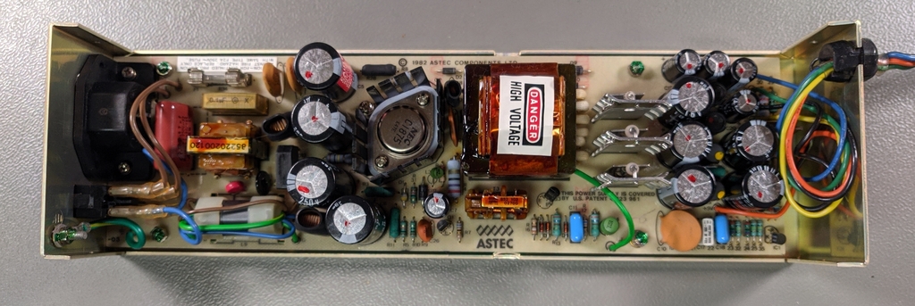
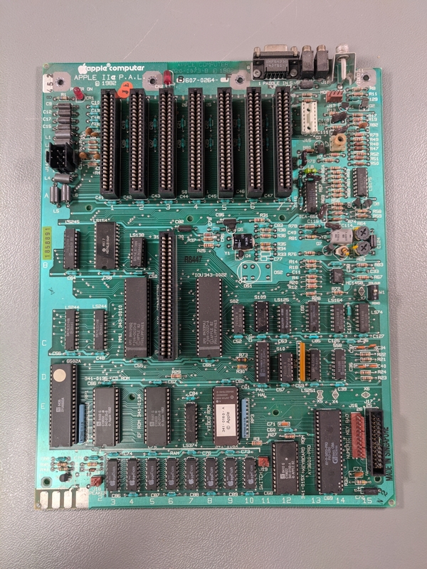
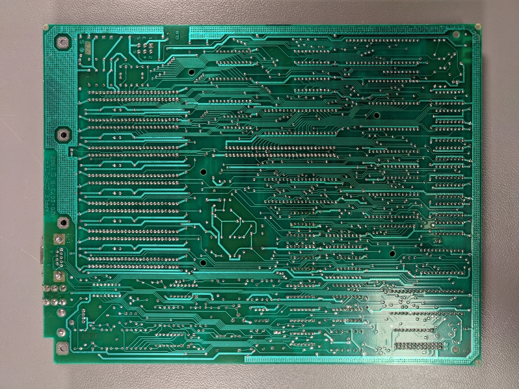
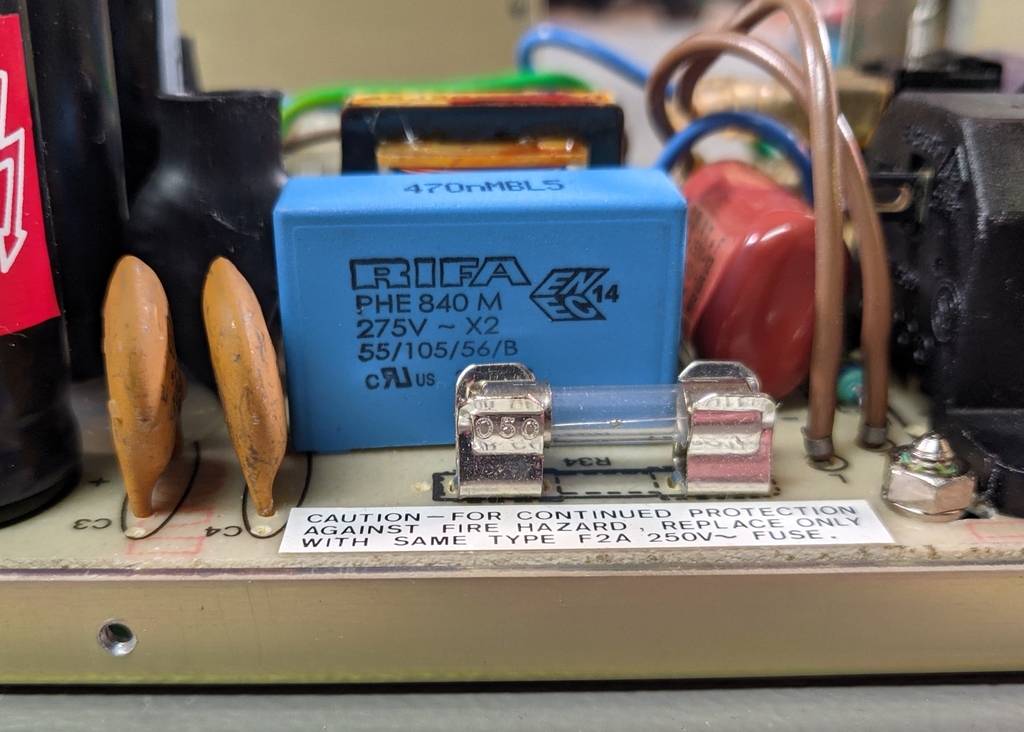
RIFA capacitor
As is often the case with computers of this vintage, a RIFA capacitor was installed in the power supply. These capacitors are well known to go bad over time and will often explode after just a few minutes of use, often not doing any major damage, but leaving a rather nasty smell.
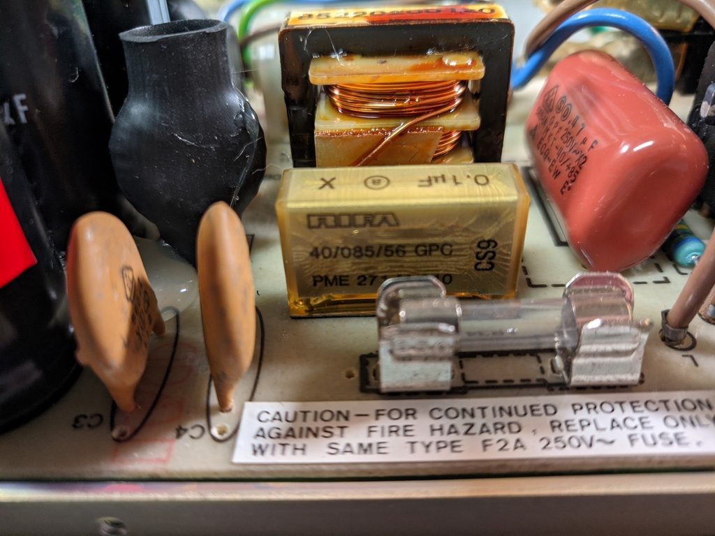
Although simply removing them usually sufficient, I like to replace them with a modern equivalent to keep everything correct.
RAM issue
Now it was time to start the troubleshooting:
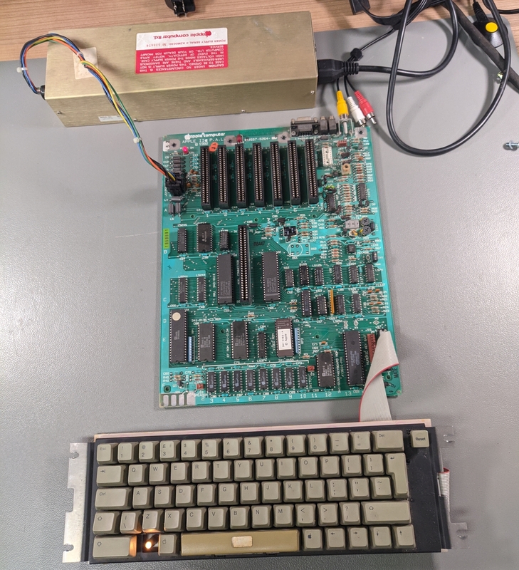
After running the built-in diagnostics, the computer only provided the error: "RAM: ", without specifying the exact address that had failed the test. So I went ahead and replaced the IC that was indicated by the diagnostics card used by the previous owner:
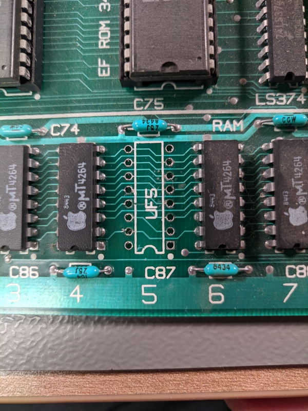
Initially after replacing the RAM IC I found that the computer didn't start at all any more. I double-checked the continuity between the RAM ICs and found that two traces had been damaged when I removed the IC. After repairing those, the computer would boot again:
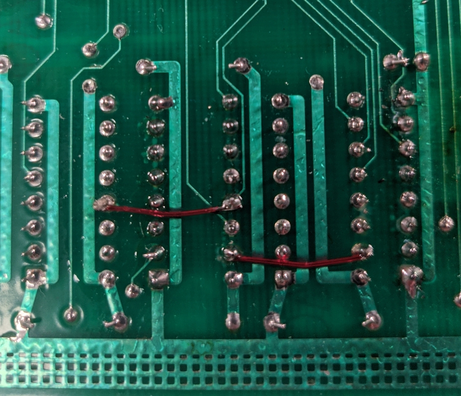
However, this did not resolve the issue and the computer is still showing the same error on the built-in the diagnostics. Since the error itself it was not very useful, I decided to hook up the logic analyser:
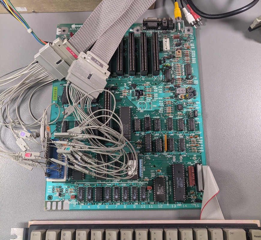
After configuring the logic analyser to trigger on the address that the CPU continuously loops on after the diagnostics failed, I was able to get all the instructions which ran immediately before the diagnostics stopped.
Using a small Python script, I compared the data being read from each memory address to what had been written to this address before.
from rpi import Rpi # https://github.com/number42net/hp-16600-16700-rpi
c = Rpi("<logic analyser IP>")
modules = c.get_modules()
analyzer = modules[0]
data = analyzer.get_listing()

memory = {}
for index, row in data.iterrows():
    addr = row["ADDR"]
    if row["STAT"] == 0x0E:
        memory[addr] = row["DATA"]
    if row["STAT"] == 0x1E and addr in memory and memory[addr] != row["DATA"]:
        print(f"Fault at {hex(addr)}, expected: {bin(memory[addr])} but got: {bin(row['DATA'])}")
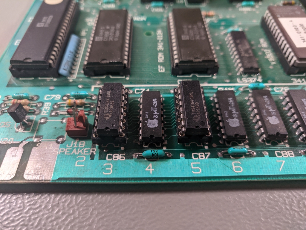
Due to the complex memory banking on the Apple II, this resulted in a few false positives, but one error clearly stood out. On one address, the least significant bit was always 0, even if a 1 had been written previously. After checking the schematics, it was clear that this bit was stored in IC F3.
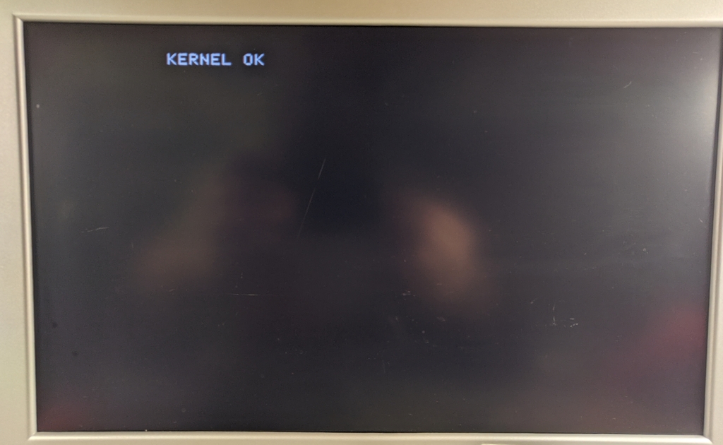
After replacing this IC as well, the self test passed with flying colours:
Serial card
The only additional card that this computer came with was an Asynchronous Serial Interface Card, model 7710A. Aside from "©1979 JTM", there is no manufacturer mentioned on the card, but the design and schematic matches exactly with a California Computer Systems (CCS) 7710 card. Considering the bodge across the driver IC and date codes on the ICs (most are around 1978-1979), I assume that this is a very early revision.
After doing some additional research, I found that CCS was co-founded in 1979 by John Mason, who also designed other boards under the JTM name.
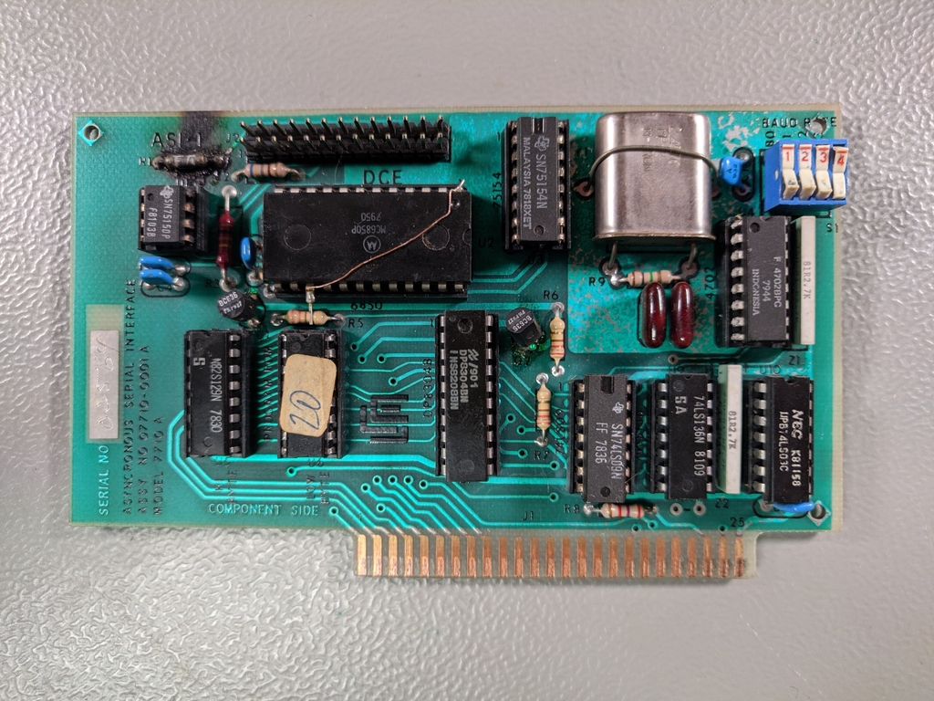
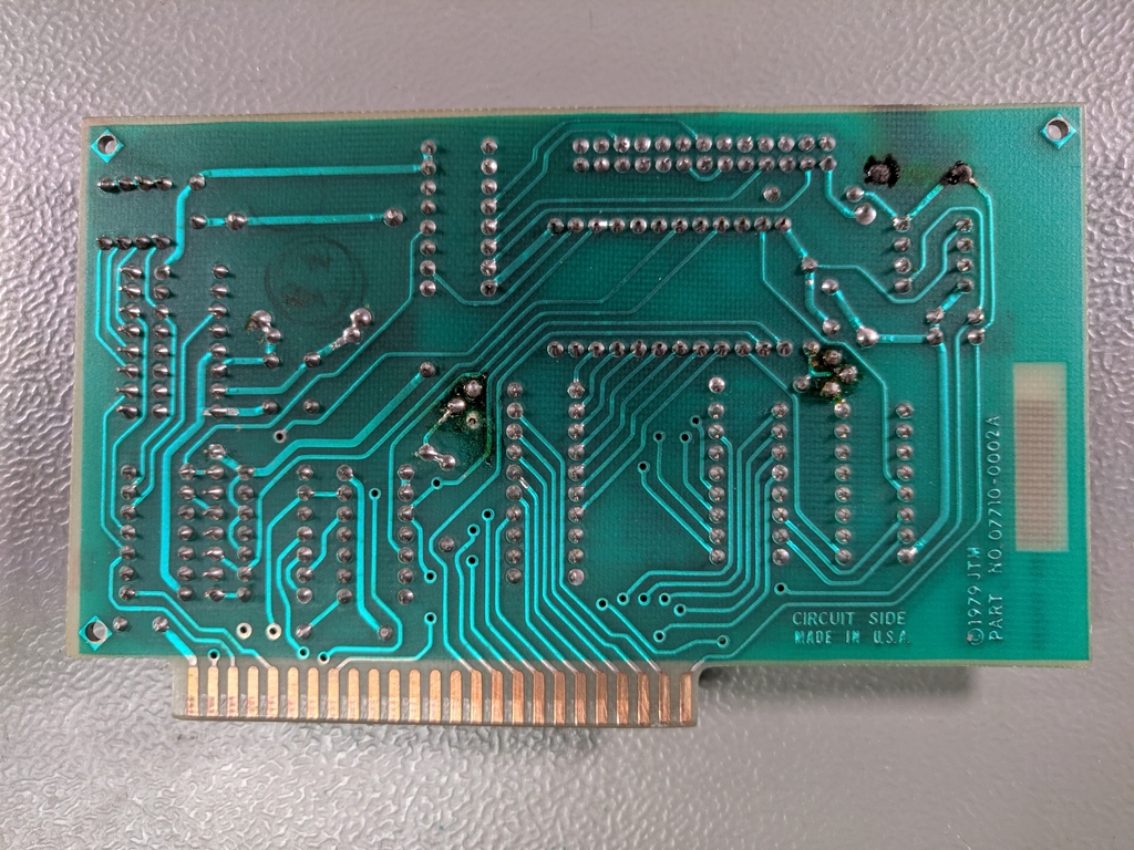
This card works differently from what you would commonly expect on a computer, it behaves as a DCE (Data Communication Equipment, like a modem), rather than a DTE (Data Terminal Equipment, like a computer or terminal). So when connecting it directly to a more modern computer, you don't need to use a NULL-modem cable.
The card had a burned out resistor connected to pin 25, which is used by a DCE to signal that it's in loop back mode for testing. According to the schematic, this was a 10ohm resistor, which was connected directly to the 12v supply (which would indicate loop back disabled). I can only assume that it was burned out, either by a device shorting it to ground or using it as supply voltage.
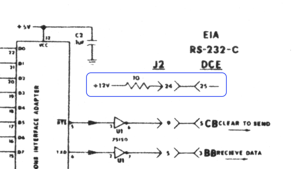
After replacing the resistor with a 10K replacement (ensuring that it wouldn't burn out again) and securing it with some UV solder resist, I started testing the card, which worked perfectly.
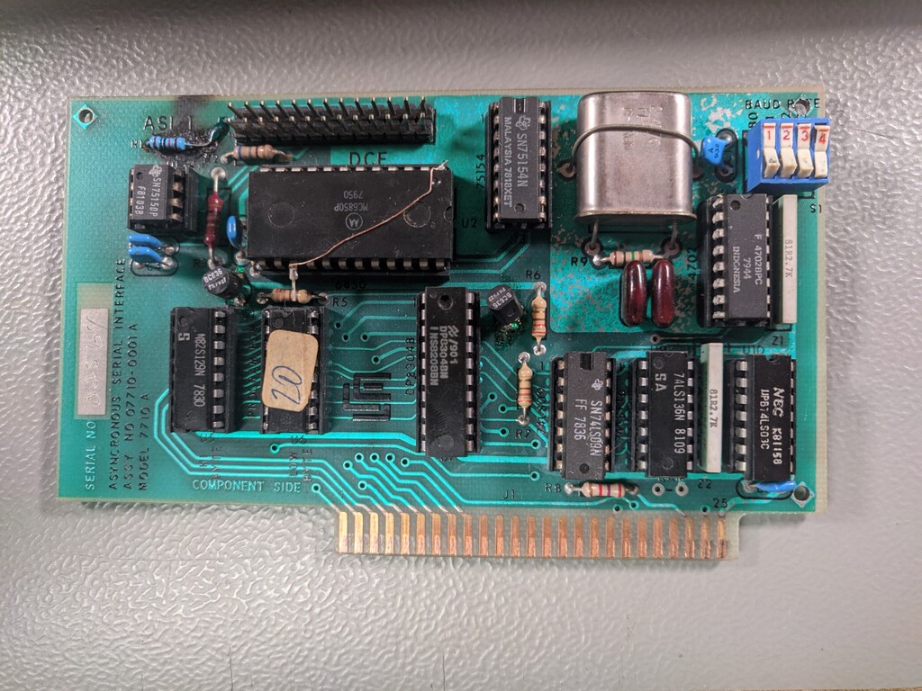
The BAUD rate is configurable through the rocker switches and is documented in the manual and the default configuration is: 8 data bits, 2 stop bits, no parity. Hardware flow control is required, the card will not transmit any data unless DTR is asserted by the remote device.